1 Purpose and Structure
1.1 Primary circuit coolant leak monitoring system is intended to monitor the leak-tight integrity of equipment and pipelines and to detect at an early stage primary circuit coolant leaks of WWER-440/1000 reactor systems when the power generating unit is in the following modes:
- start/shutdown;
- operation in power output modes;
- containment heat removal malfunction;
- «minor» leak of primary circuit coolant.
1.2 The objects to be monitored by the leak monitoring system are:
- reactor upper unit equipment;
- main circulation pipeline;
- pressurizer system pipelines;
- emergency core cooling system piping (pipeline section between the reactor system and the first back flow prevention valve; for WWER-1000 type reactor systems).
1.3 Reactor upper unit
The leak monitoring system ensures leak monitoring of the following equipment of reactor upper unit:
- Flange connectors of upper unit connecting legs;
- Seals of neutron measurement channel cases in removable flanges of neutron measurement channel connecting legs;
- seals «case-plug» of control rod drives;
- seals «plug-position indication sensor» of control rod drives;
- flange seals of reactor air ventilation.
1.4 Pressurizer system piping
Pressurizer system piping belongs to safety-related normal operation equipment and has a classified designation – 2N and equipment group – В (according to the RF Nuclear Power Engineering Rules and Standards PNAE G).
The leak monitoring system ensures monitoring of the following pressurizer system pipelines:
- connecting legs, welds and bendings of interconnecting piping of coolant feed into the pressurizer along the whole length of the pipeline;
- connecting legs, welds and bendings of piping, of pressurizer spray piping.
1.5 Main circulation pipeline
The main circulation pipeline belongs to safety-related normal operation equipment and has a classified designation – 2N and equipment group – В (according to the RF Nuclear Power Engineering Rules and Standards PNAE G).
The leak monitoring system ensures leak monitoring of main circulation pipeline in the following volume: connecting legs, welds and pipeline bendings along the whole length of the pipeline including points of welding the coolant header to the pressurizer bodies (in compliance with the Technical requirements TT 1.5.4.01.002.0050-2011. Technical Requirements to Leak Monitoring System of WWER-440/1000 Reactor System).
1.6 Emergency core cooling system pipelines
The leak monitoring system ensures coolant leak detection in case of leak-tight integrity loss of emergency core cooling system pipelines (along the whole length of the emergency core cooling system pipeline: the pipeline section from the reactor to the first back flow prevention valve).
1.7 The purpose of the system is to enhance NPP operational safety due to early detection of the coolant leak to prevent the potential pipeline break or reactor primary circuit equipment break.
1.8 List of leak monitoring system functions
The functions of the leak monitoring system in the automatic continuous normal operation mode are subdivided into:
- information functions;
- auxiliary functions.
2 Leak monitoring system structure and purpose of its constituent parts
2.1 The leak monitoring system is an integral system. It includes:
- leak monitoring system upper level;
- acoustic monitoring subsystem;
- humidity monitoring subsystem;
- leak monitoring system remote workstation (workstation included in the leak monitoring system).
2.2 Leak monitoring system upper level consists of redundant main computer that receives data for joint analysis from three independent subsystems:
- humidity monitoring subsystem;
- acoustic monitoring subsystem;
- automated radiation monitoring system (radiation safety control equipment) through the IT system of the power generating unit.
2.3 The upper level of the leak monitoring system additionally receives data from the unit IT system on the reactor system basic parameters:
- coolant temperature of «hot» and «cold» legs of each loop;
- primary circuit coolant pressure;
- on the status (availability of initiation signals) of signal indicators of upper unit flange connectors leaks;
- pressure in the space between the seals of the main reactor joint;
- pressure in the space between the seals of flange connectors of pressurizer tubular heating elements;
- balance of coolant make-up-blow-down flow in the primary circuit etc.
2.4 Each leak monitoring subsystem (humidity monitoring subsystem, acoustic monitoring subsystem) includes:
- primary transducers with attachment points;
- amplifiers or normalizing transducers of primary transducers signals;
- communication lines and devices;
- switching devices;
- data measuring units (UII) that ensure processing of data that arrive from the amplifiers or normalizing transducers and links with the leak monitoring system upper level.
The structure of the leak monitoring system software-hardware suite enables further development and upgrade of the system both in terms of measuring channels number and in terms of enhancement (upgrade) of processing and analysis functions of the input diagnostic data.
Table 1 contains the structure of the leak monitoring system hardware package intended to be installed on the reactor system V-320.
Table 1 – Leak monitoring system hardware package structure
| No. | Equipment | Designation | Number |
| 1 | Data measuring unit UII of humidity monitoring subsystem | ДКНБ.421431.032 | 1 |
| 2 | Data measuring unit UII of acoustic monitoring subsystem | ДКНБ.421431.031 | 1 |
| 3 | Temperature and humidity measuring transducer DV2TS-6T-4P-G | ТУ 4231-008-77511225-2010 | 52 |
| 4 | Acoustic sensor | ДКНБ.433649.002 | 44 |
| 5 | Test generator | ДКНБ.431117.001 | 4 |
| 6 | Acoustic transducer | ДКНБ.433649.001 | 4 |
| 7 | Amplifier UP-AE | ДКНБ.687281.047 | 44 |
| 8 | Leak monitoring system installation kit | ДКНБ.421941.136 | 1 |
| 9 | Leak monitoring system spare parts kit | ДКНБ.421943.041 | 1 |
| 10 | Leak monitoring system tools and accessories kit | ДКНБ.421944.036 | 1 |
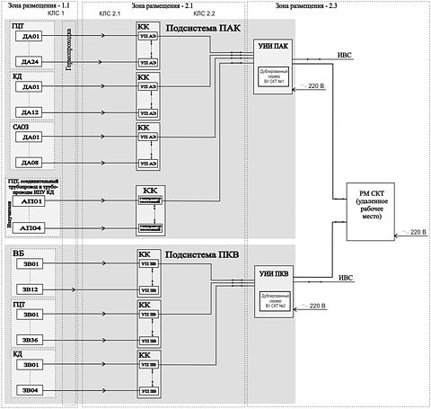 Figure 1 – Block Diagram of Leak Monitoring System Hardware Package Figure 1 – Block Diagram of Leak Monitoring System Hardware PackageBlock diagram of leak monitoring system is given in Figure 1.
2.5 Humidity monitoring subsystem
The humidity monitoring subsystem includes:
- humidity and temperature measuring transducers DV2TS-6T-4P-G intended for continuous conversion of temperature and relative humidity into a digital output signal. The humidity and temperature measuring transducer DV2TS-6T-4P-G consists of: an external humidity probe to be installed in zone 1.1 and measuring unit to be installed in zone 2.1;
- attachment points of external humidity probes;
- switching devices to accommodate measuring units;
- communication lines and devices;
- data measuring unit UII of humidity monitoring subsystem installed in the premises of zone 2.3.
2.6 Acoustic monitoring subsystem
Acoustic monitoring subsystem includes:
- Primary transducers (acoustic sensors) to be installed on the monitored equipment in the premises of zone 1.1;
- Primary transducers attachment points;
- amplifiers UP-AE to be installed in the premises of zone 2.1;
- switching devices to accommodate amplifiers UP-AE;
- communication lines and devices;
- data measuring unit UII of acoustic monitoring subsystem to be installed in the premises of zone 2.3.
3 Description of Diagnostic Principles
3.1 Humidity and temperature monitoring
The diagnostics of equipment and pipelines integrity is based on the measurements of ambient air humidity and temperature and detection of their changes in the places of monitored equipment and pipelines installation as a result of primary circuit coolant leaks. The ambient air humidity measuring technique applied in the leak monitoring system, performed by way of measurement with the help of the electrical sensor based on the electrical capacity complies with GOST ISO 8573-3.
Coolant leaks in the main circulation pipeline and pressurizer pipelines are monitored on the basis of signals from the humidity probes installed over the full length of the pipelines.
During the analysis of signals from the humidity probes installed on the main circulation pipeline and pressurizer pipelines, procedures are performed aimed at the leak detection in the monitored pipelines and if a leak is detected, the leak location is defined and the leak flow rate is evaluated.
When the main circulation pipeline and pressurizer pipelines are checked for leaks, the ambient air parameters are measured inside the pipeline thermal insulation.
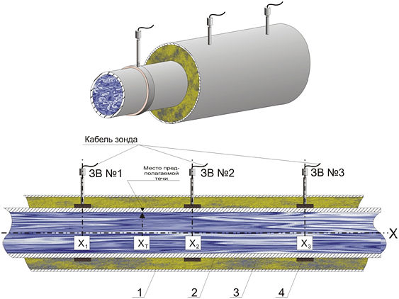 1 - thermal insulation case, 2 - pipeline, 3 – thermal insulation, 1 - thermal insulation case, 2 - pipeline, 3 – thermal insulation,
4 - humidity probe attachment pointFigure 2 – Simplified diagram of installation of external humidity
probes on a pipeline sectionSamples of air from underneath the thermal insulation case are taken to be analyzed with the help of air sleeves installed in the upper part of the pipeline as shown in Figure 2.
According to Figure 2 air sleeves are installed in the upper part of the pipelines having external probes at the end. If a leak occurs at the point хт, vapor-air mixture will fill out the insulating space and go up the air sleeves towards the externals probes having humidity and pressure sensors.
The data for the subsequent diagnostic analysis for the monitored pressurizer and main circulation pipelines with sensors installed on them will be represented by two vector arrays for each monitored pipeline section:
- n-dimensional vector of variables φi (relative humidity measurement channels);
- n-dimensional vector of variables Ti (temperature measurement channels).
3.1.1 Absolute humidity determination
Absolute humidity ρi, kg/m3, near the humidity probe is based on the values of temperature and relative humidity
| ρi = ρн ( Ti ) · | φi | , |
| 100 |
where ρн ( Ti ) - is the density of saturated steam at the temperature Ti, kg/m3;
φi - is the relative humidity, %.
3.1.2 Leak detection for a pipeline section
Humidity probe anomaly is determined on the basis of the decision rule:
if ρi(t) ≤ ρi пор – is the normal value,
if ρi(t) > ρi пор – is an anomaly,
where ρi пор – is the absolute humidity threshold value.
The timepoint of reaching the setting by i–numbered humidity probe is recorded and used further on in the calculations. The coordinates of the humidity probe installation place on the monitored pipelines are put into the database.
Let’s consider the following example of the humidity probe installation and the location of the assumed leak as shown in Figure 2.
In this case the so-called «gas – vapor front» reaches humidity probe №2 first, then humidity probe №1, and finally humidity probe №3.
The leak is recognized on the basis of the violation of the setting ρi пор by the external probes of the pipeline section, simultaneously the time of the τi setting violation is registered by the appropriate external probe. A leak message is generated with the indication of the leak location.
3.2 Acoustic leak monitoring technique
The technique of primary circuit coolant acoustic leak monitoring is based on the registration of acoustic high-frequency noise propagated over the pipeline metal, caused by the hydrodynamic and aerodynamic phenomena in case of coolant leak through the discontinuity of the monitored object. The technique of primary circuit coolant acoustic leak monitoring used in the leak monitoring system complies with GOST R 52727.
Acoustic emission waveguide sensors are used as acoustic sensors.
Acoustic emission sensors used as primary transducers are installed on the main circulation pipeline, pressurizer pipeline as well as on the emergency core cooling system pipeline section as far as the first back flow prevention valve.
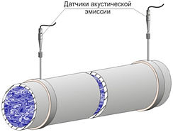 Figure 3 – Simplified Diagram of Figure 3 – Simplified Diagram of
Waveguide Acoustic Sensor
Installation at a Pipeline SectionThe simplified diagram outlining the waveguide acoustic sensor installation on a pipeline section is given in Figure 3.
The primary transducer signals arrive at converters-amplifiers that output digital signals proportional to rms values of the primary signal. These rms signals generate measurement series for further processing.
The leak monitoring algorithm is based on the principle of signal comparison with the set threshold value. In case of registering an anomaly for one or more sensors installed in a certain inspection area, a message is generated about registering an anomaly in the respective inspection area.
4 Installation of Leak Monitoring System Primary Transducers
4.1 Installation of primary transducers of humidity monitoring subsystem
The humidity monitoring subsystem sensors are installed on the reactor upper unit equipment, on the main circulation pipeline and pressurizer pipelines.
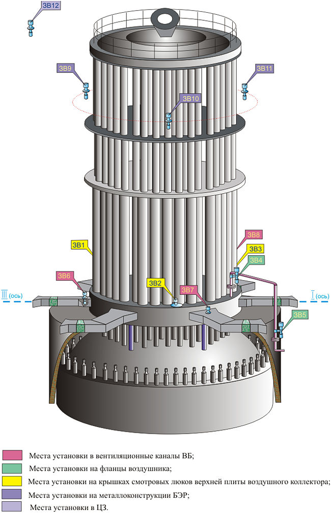
The reactor upper unit has three sensors embedded in the ventilating ducts and three sensors embedded in the lids of the inspection ports of the air header top slab, two sensors installed on the air ventilation pipeline near the flanges that are outside the thermal insulation, three sensors installed on the metal structures of electrical connection unit and one sensor is installed in the central hall.
The diagram outlining the external humidity probe installation on the reactor upper unit equipment is given in Figure 2.
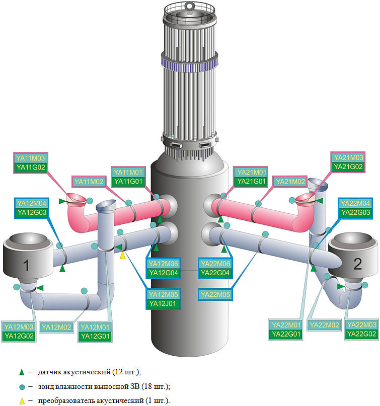
36 external humidity probes are installed on the main circulation pipelines (9 humidity probes in each loop). The diagram outlining the humidity probe installation on the main circulation pipeline is given in Figures 3, 4.
 Figure 4 – Layout Diagram of External Humidity Probes of Humidity Figure 4 – Layout Diagram of External Humidity Probes of Humidity
Monitoring Subsystem on the Reactor Upper Unit Equipment Figure 5 – Layout Diagram of Primary Transducers of Leak Monitoring Figure 5 – Layout Diagram of Primary Transducers of Leak Monitoring
System in Main Circulation Pipeline of Loop 1 and 2Four humidity probe sensors are installed on the pressurizer surge line. The diagram outlining the humidity probe installation on the surge line is given in Figure 5.
4.2 Acoustic monitoring subsystem
The acoustic sensors of the acoustic monitoring subsystem are installed on the main circulation pipeline, pressurizer system pipeline and emergency core cooling system pipelines.
24 acoustic sensors (6 sensors in each loop) and two acoustic transducers are installed on the main circulation pipeline. The diagram outlining the acoustic sensor installation is given in Figures 3, 4.
12 acoustic sensors and 2 acoustic transducers (one is installed on the surge line and the other is installed on the steam relief header) are installed on the pressurizer surge line piping (three acoustic sensors), pressurizer spray piping (five acoustic sensors) and relief piping of pressurizer pulse safety device (four acoustic sensors: one sensor on the relief header and three sensors on the steam relief piping). The diagram outlining the acoustic sensor installation is given in Figure 5.
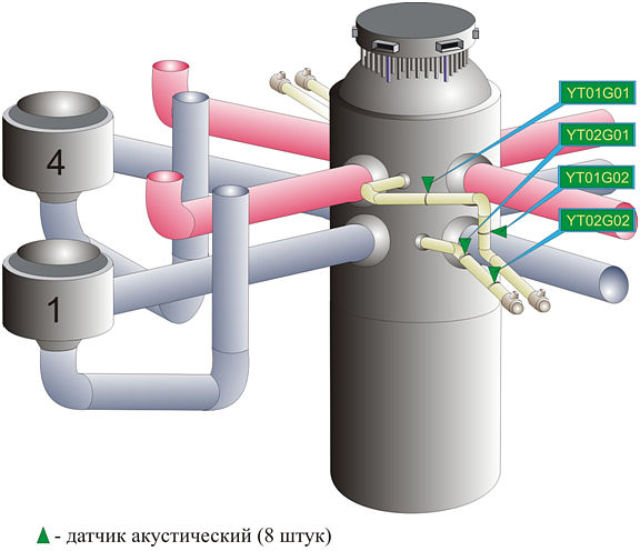
Eight acoustic sensors are installed on the emergency core cooling system piping (two acoustic sensors on each pipeline). The block diagram outlining the installation of acoustic sensors on the emergency core cooling system piping between the first and the second loops of the main circulation circuit is given in Figure 6.
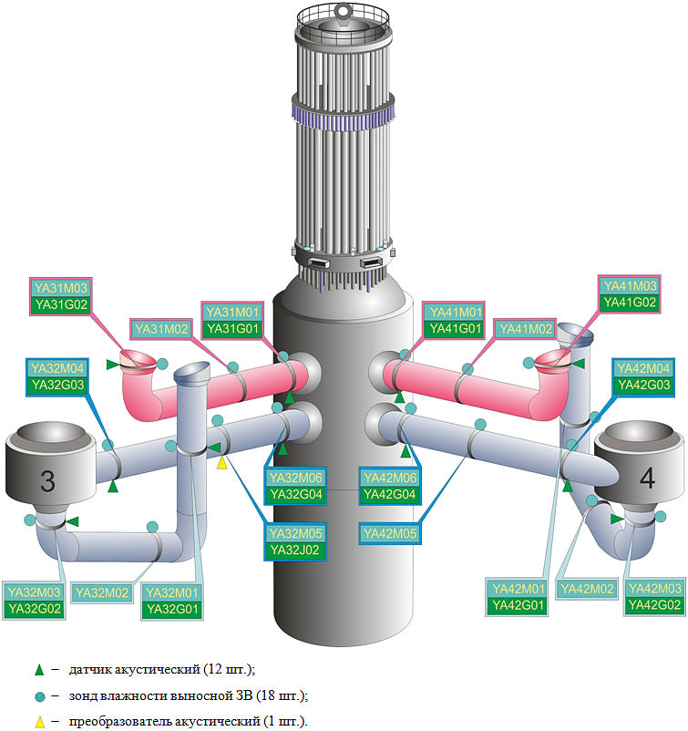
The acoustic sensors on the emergency core cooling system pipelines between the main circulation circuit third and fourth loops are installed in the same way as those given in Figure 6.
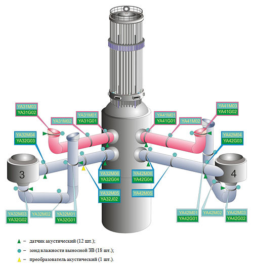 Figure 6 – Layout Diagram of Primary Transducers of Leak Monitoring Figure 6 – Layout Diagram of Primary Transducers of Leak Monitoring
System in Main Circulation Pipeline of Loops 3 and 4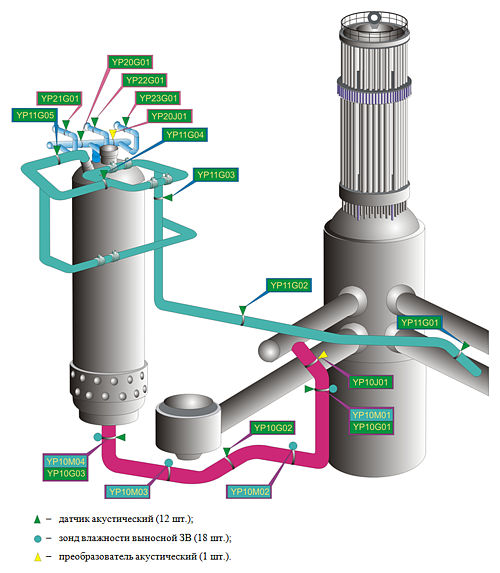 Figure 7 – Layout Diagram of Primary Transducers of Leak Figure 7 – Layout Diagram of Primary Transducers of Leak
Monitoring System in Pressurizer Pipelines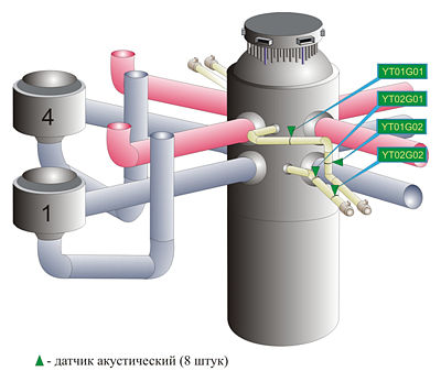 Figure 8 – Layout Diagram of Acoustic Sensors in Emergency Figure 8 – Layout Diagram of Acoustic Sensors in Emergency
Core Cooling System Pipelines (between 1-st and 2-nd Loops
of Main Circulation Circuit) |